about Filter
MCF / SAW : MCF
General
A MCF (Monolithic Crystal Filter) is a filter that works by using a mechanical combination between mounted electrodes on a piezoelectric substrate.In 1962,Former: TOYOCOM. (Present: Epson )developed the world's first MCF. Since then, TOYOCOM have developed many kinds of compact, high reliability filters covering a wide range of frequencies.
The following diagrams show the basic structure and equivalent circuits of a 2-pole MCF.
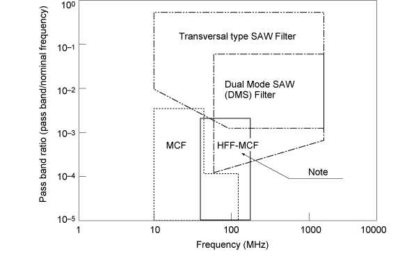
Range of nominal frequency and band pass that is made available with a MCF
Basic Structure
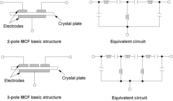
Thus, a 2-pole filter or a 3-pole filter can be made according to the number of electrodes built on one crystal plate.
A 3-pole MCF can obtain a steeper attenuation curve compared with a 2 pole MCF.
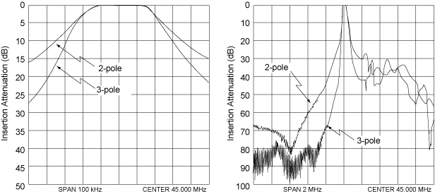
Measurement
(1) Measurement of attenuation value and group delay The attenuation value and group delay are measured with a network analyzer. A test jig with a built-in impedance matching circuit between a network analyzer (50 ohms) and a MCF (Zt) is used for the accurate measurement of filter impedance Zt.
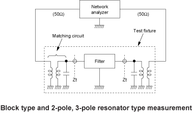
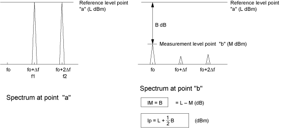
(2) Intermodulation measurement

Two methods are used for the expression of intermodulation characteristics:
IM and IP. The concept of each measurement method is explained below.
MCF / SAW : SAW
General
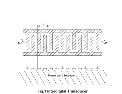
A Surface Acoustic Wave (SAW) is an acoustic wave propagating along the surface of an elastic substrate, the amplitude of which decays exponentially with substrate depth. SAWs can be generated and detected by an interdigital transducer (IDT) on a piezoelectric substrate (Fig.1). The frequency (f) of a SAW can be found by the formula f = V/λ where λ is the IDT period and V is the velocity of the wave. The transmission speed of a SAW varies with the substrate material. For example, the velocity of a SAW on ST cut quartz is about 3100m/sec. The optimum frequency range of a SAW device is from 10MHz to 2GHz. The upper and lower limits of the available frequency of SAW device are determined by the fine-pattern resolution, and the size and specification of the device, respectively.
SAW devices fall into two major categories:
SAW transversal filters and SAW resonators. (Transversal filters are equipped with input and output IDTs to utilize the propagation of SAWs, while resonators are equipped with reflectors on either side of the IDT to utilize energy-trapping by the SAW.) A SAW resonator is constructed with either one or two ports.
A one-port SAW resonator (Fig.2) has a single IDT with reflecting arrays on either side of it, resulting in efficient reflection. After having been generated by the IDT, a SAW is trapped between the two reflectors. This construction provides high-Q resonance.
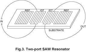
A two-port resonator (Fig.3) has a pair of IDTs flanked by a pair of reflectors, resulting in a similar high-Q resonance to a one-port resonator. Since a two-port resonator is a low-insertion loss band pass filter with a very narrow bandwidth, it can readily be used to form an oscillation circuit by building a feedback loop with a single stage amplifier. Thus, a two-port resonator is often used as well as a one-port resonator. In particular, such a two-port resonator demonstrates its real value in high frequency circuit use. The phase conditions of a two-port resonator for oscillation vary with the oscillation circuits used. Therefore when sending a purchase order for two-port SAW resonators, please indicate the phase shift value (180° or 0°)at a nominal frequency.
SAW filters are classified into two types: one is a transversal SAW filter suitable for wide band characteristics, and the other is a SAW resonator filter suitable for narrow and middle band low-loss characteristics.
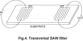
The SAW transversal filter (Fig.4) is equipped with input and output IDTs. The SAW, generated by the input IDT, travels along the surface of the substrate to be detected by the output IDT.The frequency response of a SAW transversal filter is characterized by apodization of the IDT, so that the required response can be obtained without having to adjust the terminating impedance.
One type of SAW filter is a double-mode SAW
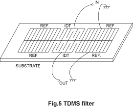
filter (DMS) which utilizes the acoustic coupling of two IDTs. DMSs are divided into two types: one is a transverse coupled double mode SAW (TDMS)
filter (Fig.5) that has two IDTs placed in a close and parallel configuration on a single substrate.
The other is a longitudinal coupled double mode SAW (LDMS) filter (Fig.6)
that has two IDTs placed in a longitudinal configuration on a single substrate.A
LDMS realizes a broader pass band and lower insertion impedance than a TDMS.
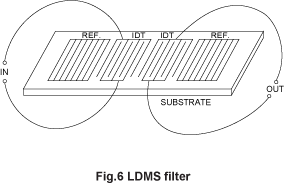
The pattern configuration of the LDMS filter is almost the same as that of the two-port SAW resonator (Fig.3). However, the two-port SAW resonator is designed to suppress higher order resonance modes, and to use only the 1sT resonance mode. On the other hand, with the LDMS filters, both the 1sT mode and 2nd mode are designed to be used for generating large responses.
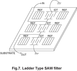
Ladder type SAW filters have also been developed as another type of resonator filter. As shown in Fig.7, a ladder type SAW filter consists of a band pass filter connecting several one-port SAW resonators into a ladder configuration. A ladder type SAW filter can realize the necessary filter characteristics by the selection of the number of SAW IDT and the resonance frequency of each IDT, etc.
The optimum material for the SAW substrate is selected from various materials to realize the requested characteristics. Crystal is used for SAW resonators and narrow band SAW filters, which require frequency stability, because of its excellent temperature characteristics. On the other hand, materials such as LiTaO3 and LiNbO3 are used for wide band SAW filters because of their high electro-mechanical coupling coefficient. In this way, we can utilize the best material to meet the customer's requirements in our filter design.
