Gyro sensor checkpoints
Here, we present gyro sensor checkpoints that specifications don't show.
Gyro Sensor Checkpoints
An accurate gyro sensor is a stable gyro sensor.
The keys to stable gyro sensors are as follows:
1. Low noise level
2. Stability over temperature
2-1. Bias stability over temperature
2-2. Scale factor stability over temperature
3. Vibration and shock resistance
3-1. Resistance to vibrations other than angular velocity
3-2. Shock resistance

1. Low noise level
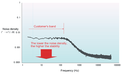
2. Stability over temperature
2-1. Bias stability over temperature
Look at the graph and observe the effect that changes in temperature have on the initial value (the zero point, i.e. the value output when angular velocity is not being applied).
A gyro sensor that has a stable bias temperature characteristic exhibits little or no variation in bias over a temperature range when the gyro sensor or the product in which it is mounted is in a static state. It can thus accurately sense that it is not moving.
In this graph high stability is indicated by a line that is as straight as possible and that has a minimal range of deviation.
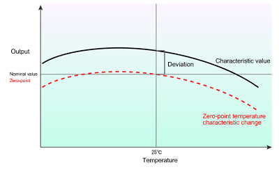
The temperature characteristic of zero-point voltage is expressed by an ordinary amount of change. The reference value for specifications is 25 degrees Celsius. This is expressed as an amount of change of the temperature characteristic (red line).
Every gyro sensor outputs its own value at 25 degrees C (that is, they exhibit some variation at room temperature), so this variation among individual gyro sensors needs to be taken into account at system calibration.
2-2. Scale factor stability over temperature
The story is the same for scale factor sensitivity.
As shown in the graph below, check how output per deg/s (sensitivity error: mV/ (°⋅s-1) unit) over the operating temperature range.
Corrections have to be applied to cancel out this change, placing a set-up burden on customers.
Here too, stability is indicated by a graph line that is as straight as possible and has minimal deviation. Higher stability can lighten the burden for correction by the system.
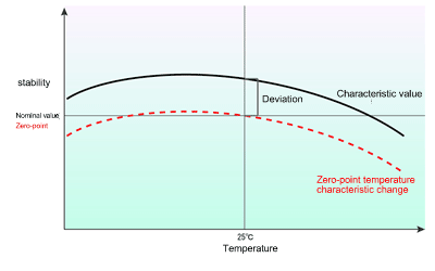
Sensitivity calibration is difficult, and places a significant burden on equipment.
Sensitivity error produces proportional errors in the magnitude of an angular velocity.
Manufacturers can provide sensitivity and other data.
3. Vibration and shock resistance
3-1. Resistance to vibrations other than angular velocity
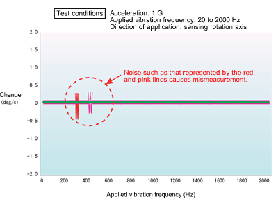
The graph below is a measurement sample.
The ability of a gyro sensor to operate without being affected by vibrations from sources other than angular velocity (e.g. acceleration) leads to high stability.
When the gyro sensor is at the zero point and a vibration frequency different from that of angular acceleration is applied, noise such as that indicated by the red and pink lines circled in the graph can be generated. This noise causes measurement errors.
This type of check is also an important point in terms of stability.
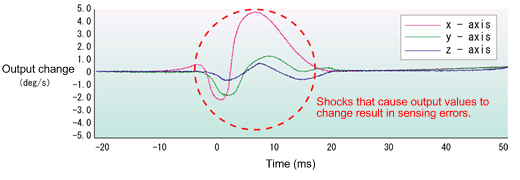
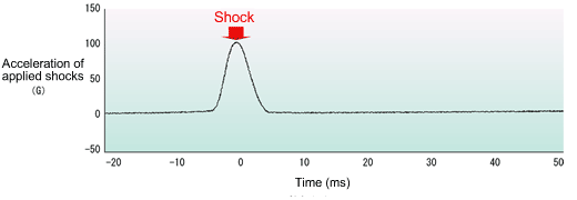
3-2. Shock resistance
Data for shock resistance needs to be checked.
Shock resistance test may be used to check (1) the impact a sensor can withstand before breaking; and (2) the impact a sensor can withstand before its characteristics change.
You need to carefully check shock resistance figures presented in specifications and the like to ascertain which type of resistance is meant before selecting a sensor.
Resistance to damage and characteristics that are unaffected by physical shocks are both keys to high stability.

As we have seen, it is important to carefully check the keys to stability when choosing a gyro sensor.
