Part5. Curiosity and fervent study lead to great inventions
February.2013
The reluctant employee
Yuzo Nakazawa had studied microwave communication, a leading-edge technology at the time, at Tohoku University. After graduating, he hoped to contribute to the reconstruction of post-war Japan by leveraging this new knowledge in microwave communication technology. With this in mind, he accepted a position at ‘Toyo Communication Equipment Company,’ enticed by the mention of ‘communication’ in the company name.
Upon graduating in 1953, he was ready and enthusiastic to start working for the company, assuming that one of its many departments would be for wireless communication devices. With the highest of expectations, he believed unconditionally that he would join that department and then proceed to demonstrate the full extent of his abilities. However, his expectations deflated instantly upon being informed that he would be joining the ‘Quartz Department.’ Shocked, he silently wondered if he had made the right career choice, unable to understand why he would have been selected to work with quartz instead of wireless communication devices.
The only thing he knew about quartz at that time was that it was a material used for ornaments, decorations and hanko seals. It was a disappointing blow to his ego to have to work for a department involved with such a trivial material.
Fire leaves employees with nothing to do
As if to add insult to injury, a terrible incident occurred shortly after Mr. Nakazawa joined the company. A fire broke out in the building that housed Toyo Communication Equipment Company's Quartz Department, and the workplace was lost. As a new recruit, the first task assigned to Mr. Nakazawa had been the inspection of quartz devices. However, with all quartz devices and testing equipment lost in the fire, it was impossible to accomplish this task. He was at a loss as to what he could do.
It was during this time that he recalled an issue that had been bothering him since he began working in the Quartz Department: there was ‘no one at the company who was truly familiar with theoretical concepts relating to quartz devices,’ even though there were plenty of engineers there with knowledge relating to design, manufacture and testing. In other words, the Quartz Department of Toyo Communication Equipment Company at that time was composed of a group of ‘highly skilled craftspeople.’ The principle reason for this was the company's relationship with its then-parent company, Nippon Electric Company, Limited (now known as ‘NEC Corporation.’) The corporate structure of this parent company placed Toyo Communication Equipment Company in charge of the design, manufacture and overall development of quartz devices, with the result that very few employees at the subsidiary were well-versed in quartz device theory.
With the testing equipment lost in the fire, Mr. Nakazawa would be unable to perform his assigned tasks for the foreseeable future. He therefore decided to study quartz device theory from scratch. With this resolved determination, he proceeded to read every book about quartz devices that he could possibly find. In particular, he read ‘Atsudenki to Koushuha*1) from cover to cover, the only technical book about quartz device theory in existence at that time. Following the fire, it took approximately one year before the new company building was complete. Mr. Nakazawa took this opportunity to study intensively, until he eventually had more knowledge about quartz devices than anyone else at the company.
*1) The author of ‘Atsudenki to Koushuha’ (‘Piezoelectricity and high frequency’ in English) was Issac Koga, the pioneer of crystal units in Japan. Mr. Koga was a professor at Tokyo University and at Tokyo Institute of Technology.
Entrusted with an important role
At the time Mr. Nakazawa joined the company, quartz filters in Japan were only being used in very limited applications. The quartz devices being manufactured at Toyo Communication Equipment Company were simply crystal units*2). Although the company also manufactured filters, these were LC filters. LC filters achieve the desired frequency characteristics by combining an inductor (‘L’) with a capacitor (‘C’). These are not suitable as narrow bandwidth filters because it is not possible to obtain high resonance sharpness (‘Q,’ or ‘quality factor’).
Around two or three years after Mr. Nakazawa joined the Toyo Communication Equipment Company, they were approached by Nippon Telegraph and Telephone Public Corporation (NTTPC, now known as Nippon Telegraph and Telephone Corporation or ‘NTT’) with the idea of developing a 450kHz narrow bandwidth filter capable of handling transmission-line pilot signals*3). This filter was to be extremely narrow with a passband of several hundred Hz, while a high level of ‘Q’ (which determines the ‘sharpness’ of the filter and the insertion loss) for frequency stability in ambient temperatures would also be indispensable. These levels were not attainable with LC filters.
The only way they could meet this request would be to utilize their quartz filter technology. However, no one in Japan had succeeded in creating a narrow bandwidth filter that leveraged the inherent properties of quartz materials. In other words, this new challenge would be the first of its kind in Japan. Mr. Nakazawa was the person selected to be in charge of the project. He was overjoyed at being tasked with such an important role despite still being in his twenties, and delighted to finally be given an opportunity in which he could demonstrate his abilities 120 percent.
However, as the first attempt of its kind in Japan, development was not without its complications. The biggest challenge was going to be how to achieve crystal units that had stable characteristics as well as a high Q factor. The low frequency of 450kHz required the use of crystal units with a contour vibration mode. A contour vibration mode would mean that the entire outer periphery of the quartz substrate would vibrate, so there was no suitable location from which to support it. Although the periphery contained sections that could be used for vibration, this would be impeded if those sections were used for support, and this would result in a lower Q factor.
They decided to create a small indentation in a section near the center of the quartz substrate that did not vibrate at all. They then pressed a needle-like spring into the cavity to create a structure that facilitated conduction by making contact with the spring whilst retaining the substrate. The problem with this structure was that the slightest vibration or impact would cause the state of contact to change, which would also result in changes to the characteristics. If the characteristics could not be stabilized, it would not be possible to use the filter in applications that demanded high reliability.
Just as he was puzzling over how to resolve this issue, Mr. Nakazawa received a request from his boss to transfer temporarily to the Electrical Communication Laboratory of NTTPC. The objective was to acquire the necessary retention techniques for stabilizing the characteristics of crystal units that use a contour vibration mode, as well as to obtain a higher Q factor. Shortly before this, NTTPC had been able to confirm the importance of stable characteristics and a high Q factor in crystal units that use a contour vibration mode, and had been involved in developing retention techniques under the guidance of Tokyo University. This gave rise to ‘wire mount*4). technology, which involved attaching a wire lead to the center of the quartz substrate and supporting the substrate by suspending it from the lead. They had achieved great improvement in the stabilization of characteristics whilst maintaining a high Q factor by switching to a method of direct adhesion to the lead, instead of contact with the needle-like spring.
Mr. Nakazawa wholeheartedly threw himself into the new development efforts until he had perfected the wire mount technology and succeeded in developing the 450kHz narrow bandwidth filter that NTTPC had requested. This filter was then used in NTTPC's transmission lines at every important location throughout Japan.
*2) Crystal units manufactured in those days were almost exclusively AT-cut or BT-cut thickness-shear mode resonators (TSMRs). ‘Cut’ is the term applied to the angle when a substrate is cut out of the quartz crystal. The ‘AT-cut’ was invented by Issac Koga, while the ‘BT-cut’ was invented by Hiroshi Yoda of Toyo Communication Equipment Company. The frequency range of crystal units manufactured using these cuts was around 1M to 40MHz, and applications included crystal oscillators for wireless devices.
*3) When transmitting signals, a corrective process was required to ensure that signal levels would be approximately the same, regardless of the transmission destination. During this process, the signal used to monitor signal levels was referred to as the ‘pilot signal.’
*4) ‘Wire mount’ was a technology developed in around 1952 to hold or retain crystal units so that low-frequency crystal units with a contour vibration mode and high Q factor could be achieved. Development took place at the Electrical Communication Laboratory of Nippon Telegraph and Telephone Public Corporation (now known as ‘NTT’) under the guidance of Dr. Noboru Takagi and Dr. Morio Onoe, professors at Tokyo University. According to Mr. Nakazawa, "this was a groundbreaking technology at that time."
Japanese spirit with Western learning
Mr. Nakazawa had captured a major success with his development proposal for NTTPC. Although he was pleased with the results, he didn't have time to rest on his laurels. Since partway through his involvement in acquiring the wire mount technology, he had been unable to stop thinking about a particular device.
He had continued to study quartz devices independently even after completing his year of intensive study whilst awaiting the completion of the new company premises. It had become his daily custom to read academic journals and technical publications from the U.S. One day, he found an interesting article about a device known as a mechanical filter, which used metal (iron). This device had been developed by U.S. firm, Collins Radio Company (now known as Rockwell Collins, Inc.).
This metal-based mechanical filter comprised several cylindrical iron resonators, connected by couplers. When a signal was input to the filter, the frequency signal component determined by the external dimensions of the resonator could be singularly extracted from the output. The filter characteristics obtained were high, and it was also possible to achieve filter characteristics with good ‘sharpness,’ indicating that the difference in frequencies between the passband and the stopband was extremely small. However, there was also a drawback: the thermal characteristics were poor. A change in the operating temperature would result in drastic changes to the filter characteristics, with the result that radio reception characteristics would deteriorate.
The cause of this defect was in the metal (iron) material, as a change in the ambient temperature would cause the material's characteristics to change. This would inevitably lead to changes in the filter's characteristics. Although the metallic material actually used was of course a composite chosen for its thermal characteristics, it still could not compare to quartz material in terms of thermal stability. The material characteristics of quartz barely changed at all, even when there was a change in the ambient temperature, and furthermore, it was much easier to make quartz filters smaller.
While at the Electrical Communication Laboratory of NTTPC, Mr. Nakazawa had had a flash of inspiration: ‘We could develop a crystal unit with a high Q factor by using the wire mount technology I'm studying now. Then, if we can achieve the idea of a mechanical filter that mechanically joins multiple units using quartz material, we should be able to develop a compact filter that achieves both excellent filter characteristics and thermal characteristics.’ Without a pause, he quickly tackled the next development issue, which resulted in the creation of the ‘crystal mechanical filter (‘CM filter’)*5). This CM filter was manufactured by processing the quartz substrate into an ‘H’-shaped filter element and functioned by using the long thin sections on the left and right sides as resonators (Figure 1). The middle portion connecting the two sides fulfilled the role of the coupler. This was precisely the ‘mechanical filter achieved using crystal (quartz)’ that Mr. Nakazawa had envisioned.
This filter was released on the market as a 455kHz intermediate frequency (IF) filter for single-sideband (SSB) modulation in radio communications. The use of quartz material meant that not only were good filter characteristics achieved, but thermal characteristics were also excellent. As this was the first filter to offer properties of this caliber, it sold extremely well throughout the world. Furthermore, this technology received the honor of being granted the Notable Invention Award from the Science and Technology Agency.
*5) Professor Seiichi Honda of Ibaraki University, who was engaged as an expert engineering advisor to Toyo Communication Equipment Company at that time, provided guidance in the development of CM filters.
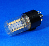
Figure 1 - Experimental sample of the development model CM filter
When development first began, the CM filter was in the shape of the letter ‘H’ (two elements). However, to make the filter's physical characteristics even steeper, they created a prototype for experimentation using crystal units with four elements. Wires (four in total) were connected to the central portion (front and back) of each of the golden elements (gold electrodes) on the outermost surface. These wires were then used to suspend (wire-mount) the crystal units. Note that after productivity and other factors were considered, two-element crystal units were ultimately adopted for volume production.
CM filters prove to be unsuitable
When CM filters first began to be sold in Japan, Mr. Nakazawa's boss traveled to the United States on business, with the objective of expanding the business overseas. Upon his return, he brought back a souvenir of a 10.7MHz quartz filter that was being sold in the U.S. for very high frequency (VHF) radios.
Shortwave radios convert shortwave signals of around 10MHz to baseband signals via an intermediate frequency (IF) of 455kHz. Accordingly, 455kHz IF filters were widely available in the Japanese domestic market. However, VHF radios needed two steps to convert a signal of around 100MHz to a baseband signal via intermediate frequencies: first converting to 10.7MHz and next to 455kHz. It was a revelation for the Japanese engineers to see a 10.7MHz IF filter for VHF radios, which were a new application for this technology.
This IF filter was composed of an AT-cut crystal unit and passive components, including an inductor and a capacitor. Toyo Communication Equipment Company was determined not to be left behind. They had also started out by combining a crystal unit with passive components, similar to the U.S. IF filter. However, VHF radios had originally been developed for portable applications, and there was urgent demand for smaller radios. Accordingly, existing IF filters were too big for this purpose, and the importance of being able to make smaller devices could not be overlooked. Once again, the spotlight was placed on Mr. Nakazawa.
When he had first begun with the development of CM filters, Mr. Nakazawa had considered applying the principles of these filters without making any changes. However, things did not proceed according to plan, and he was unable to obtain the desired filter characteristics.
The cause was the difference in frequencies. The intermediate frequency used in radios was 455kHz, while that used in the first step for VHF radios was 10.7MHz. He fine-tuned the characteristics of the CM filters by mechanically shaving the length and thickness of each of the left and right-hand side resonators. However, because the external dimensions became smaller as the frequency became higher, a better degree of accuracy was demanded for the adjustments. The frequency was too high by at least double digits, which was already a level that could not be handled by the workers. This meant that they could not obtain their desired filter characteristics.
A major invention for the century
Despite this, Mr. Nakazawa did not become flustered – in fact, he already had a plan in mind. Once again, he was thankful for being blessed with a passion for research.
Out of sheer technical interest, he had asked one of his junior staff to thoroughly investigate exactly how AT-cut quartz substrates vibrated. This resulted in the discovery that these substrates have many different vibration modes, known as ‘inharmonic modes,’ in which the displacement direction of the vibration splits into multiple directions within the electrodes.
To briefly explain vibration modes – when an alternating electrical charge is applied to electrodes corresponding to the front and rear of a quartz substrate, it will vibrate at a frequency that corresponds to its thickness. The vibration energy concentrates at the center of the electrode and decreases as it travels towards the edges of the substrate. The most fundamental mode is the first-order mode with its uniform displacement direction within the electrode. Simultaneously, a second-order mode will vibrate by splitting the displacement direction into two opposing areas, and likewise a third-order mode will split into three areas, with excitation also occurring for vibration modes of higher orders. The vibration frequency of each of these vibration modes differs only slightly, but becomes higher as the order increases.
Mr. Nakazawa skillfully used these vibration modes to his advantage. The structure of the filter he developed next was exceedingly simple, with just one set of adjacent counter electrodes mounted in the center of a quartz substrate. One of the electrodes functioned for input, while the other was for output. When a signal was applied to the input electrode, it would excite a vibration that would then leak between the two counter electrodes and travel, to be detected as an electrical signal by the output electrode. In other words, it functioned as a filter. Mr. Nakazawa further utilized the second-order mode vibrations to create a design that could regulate the passband of the filter according to the vibration frequency of the first-order and second-order modes.
By utilizing the convergence of vibration energies between the two resonators (units), he was able to create a filter from the multiple vibration modes generated. The basic thinking behind this concept was no different to the CM filter, although the element structure in this newly-developed filter was infinitely simpler, which translated to being much easier to make smaller. Furthermore, it was also easy to adjust the filter characteristics. The only aspects in need of adjustment were the shape of the two electrodes and the thickness of the quartz substrate. Both these features could be adjusted easily using conventional manufacturing techniques.
It seemed that Mr. Nakazawa had successfully created one of the major inventions of the century: a much dreamed-of filter with excellent filter characteristics that was also compact and easy to adjust (Figure 2). In 1962, Mr. Nakazawa presented his idea at an academic conference in the U.S. (Figure 3), where he was showered with accolades. Following the presentation, he suddenly found that researchers from all over the world were lining up to learn more details from him.
Thereafter, he named the newly-developed filter the ‘High Frequency Crystal Mechanical (HCM) filter,’ and commercialized it. Note that while ‘HCM filter’ was the registered trademark of the Toyo Communication Equipment Company, this filter was generally referred to within the quartz device industry as the ‘monolithic crystal filter (MCF).’
MCFs were first adopted as IF filters for VHF radios. Later, as wireless communication technology began to evolve, the industry demanded higher IF frequencies. Accordingly, the center frequency of MCFs was gradually increased from 10.7MHz to 21.4MHz, 32.1MHz and eventually to 45MHz. There was a corresponding sharp rise in the market scale, and Mr. Nakazawa came to be widely known throughout the wireless communication equipment and quartz device industries as the ‘father of MCFs*6).’
*6) The development of MCFs was highly praised, and in 1974 Mr. Nakazawa received the Japanese Patent Office Commissioner Award for the invention of the ‘thickness shear vibration-type quartz electromechanical filter.’ In 1993, he received the Distinguished Service Award for Science and Technology from the Science and Technology Agency (now part of the Ministry of Education, Culture, Sports, Science and Technology) for the ‘development of a high-frequency dual mode filter.’
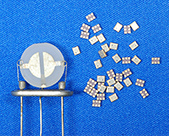
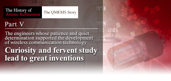
Figure 2 - The HCM filter in its initial development
Two electrodes were mounted in the center of the quartz substrate. One of these electrodes then converted electrical signals to mechanical vibrations. These signals traveled across the interelectrode gap, and the remaining electrode restored the vibrations to electrical signals. A common terminal was soldered to the holder (retainer) for the crystal units, which formerly comprised two terminals, for use in experiments with filters. Despite being an experimental sample to check operations, the crystal substrate had a diameter of 13mm. A comparison with present-day products gives a true feel for just how much progress has been made in the downsizing of these devices.
Figure 3 - The HCM filter is first mentioned in a scholarly article
A paper on the HCM filter was first submitted to the 1962 Frequency Control Symposium. This paper noted various aspects of the filter, including its operational principles, equivalent circuits, parameters that affected its properties and examples of its characteristics. This symposium continues to be held annually.
From MCFs to SAW filters
Unfortunately, even a groundbreaking invention such as the MCF had its limitations. In this case, the MCF was unable to cope with frequencies exceeding around 70MHz. This was because it was difficult to process the quartz substrates any more thinly using the technologies of that time. They therefore needed to implement new ideas once again if they were to successfully create an IF filter for frequencies higher than 70MHz.
Mr. Nakawaza next turned to surface acoustic waves (SAWs). SAWs would enable compatibility with higher frequencies by narrowing the intervals between the comb-shaped electrodes known as IDTs (inter-digital transducers) created on the surface of the quartz substrate. It was an obvious choice for any engineer involved with quartz devices, and their rivals also promptly began work on SAW filters. There was little hope of success if they only began developing conventional SAW filters at this late stage – they needed to add something special. They wanted to make an antenna-stage filter for pagers, which demanded a more compact size. The VHF-band filters needed for such applications could not possibly be achieved using MCFs.
Mr. Nakazawa then attempted to implement MCF principles in SAW filters. He placed two SAW resonators adjacent to each other and found that the acoustic coupling between these two resonators excited two different resonance frequencies: ‘f1’ (corresponding to first-order vibration mode) and ‘f2’ (corresponding to second-order vibration mode). Using these resonance frequencies, he achieved a filter that functioned using the same principles as MCF.
Until then, SAW filters had used a technique known as the ‘transversal’ type. This involved the crafting of IDTs on the left and right sides of the quartz substrate that could excite SAWs of a certain frequency. When an electrical signal was input to the left-side IDT, it was converted to acoustic waves (SAWs) that traveled across the substrate's surface to be reconverted to an electrical signal at the right-side IDT. In other words, it allowed only a specified frequency signal component to pass through. According to Mr. Masaki Tanaka, who had been involved in the development of SAW filters under Mr. Nakazawa, the biggest issue with transversal-type SAW filters was that they had an extremely large insertion loss of around 20dB. However, they succeeded in drastically reducing this insertion loss to only around 2 to 3dB, by applying the principles of MCF.
This was a huge breakthrough, and the new SAW filter was launched commercially in 1984*7). As soon as it was commercialized, the SAW filter became a major issue within the wireless communication industry, because if SAW filters were adopted, it would become possible to produce wireless communication devices that were significantly smaller and cheaper.
Until that time, wireless communication devices such as pagers had adopted a double conversion method to convert IFs in two steps when converting RF signals to baseband signals. By using the newly-released SAW filter at the RF stage, it would now become possible to convert IFs in a single step, because steep filter characteristics could be obtained in the high frequency range. This would mean that fewer components were required, which in turn would lead to a dramatic reduction in the external size and cost.
Almost instantly, the new filters were adopted for use in pagers. According to Mr. Nakazawa, the result was that "virtually all pagers were using our company's SAW filter."
*7) In addition to Yuzo Nakazawa and Masaki Tanaka, contributions to the research and development of SAW filters were also made by Takao Morita and Yoshitaka Watanabe.
In pursuit of the best material for the job, they moved on yet again to another material
The use of SAWs had paved the way towards higher frequencies. However, the SAW filters that had been developed up until that stage had all had small fractional bandwidths (the ratio of passband width to center frequency). This was because of the constraints imposed by the physical properties of quartz, the material used in the substrate. Although quartz was highly stable, it was not suited to filters with a large fractional bandwidth.
If they could achieve a SAW filter with a wider band, they would be able to replace the ceramic filters used as RF filters in mobile telephone handsets. This would enable them to provide a significant contribution towards making mobile phones smaller and lighter. Not only that – the market scale was incredibly large, and it would be extremely appealing to the company from a business perspective.
If quartz was unsuitable, they were convinced they would find a different, better material. In order to obtain useful characteristics, they decided to try out new materials rather than adhere only to quartz, the material they had become so familiar with. They tested materials such as lithium tantalite (LiTaO3) and lithium niobate (LiNbO3). They also rearranged the resonators to modify the acoustic coupling system, which enlarged the fractional bandwidth tenfold. However, the values they were now achieving were still insufficient for the demands of mobile phones.
‘Wider bandwidth’ became the new motto of Mr. Nakazawa and his research group. Their experiments and discussions continued with the aim of accomplishing this goal, until they finally reached a conclusion: ‘The frequency difference between the first-order mode and third-order mode is larger than the frequency difference between the first-order mode and the second-order mode. If we concentrate on this, we should be able to achieve wide-band SAW filters.’ This was the concept that led to their next breakthrough.
They now had a new substrate material, a new acoustic coupling system and a new resonance mode. They married these different features together to complete their wide-band SAW filter, suitable for use in mobile phones. They immediately launched this product on the market, and the response was as they had predicted. The SAW filter was received extremely well, and they had succeeded in securing a big new business.
Thereafter, they continued to polish this technology, and successively commercialized wide-band SAW filters that minimized loss even in high frequency ranges such as 1GHz and 2GHz. This enabled the company to carve out an overwhelmingly strong position for itself in RF filters for mobile phones.
Leading on to the next generation
Their success with SAW filters had brought an unexpected byproduct to Toyo Communication Equipment Company: advanced know-how in photolithography technology.
SAW filters used photolithography technology to craft the IDTs on the quartz substrate. They realized that they could employ this technology to thinly shave the quartz substrate in order to enable higher frequencies in crystal units and MCFs. The conventional machining techniques they had used until then had only allowed them to handle up to approximately 70MHz, but by chemically shaving only the vibrating portion in the center of the quartz substrate, they were at last able handle higher frequencies (Figure 4)*8).
This manufacturing technique was known as ‘High Frequency Fundamental (HFF),’ and was later used in high frequency crystal units. This became the cornerstone of another new technology known as ‘QMEMS,’ which was developed after the company was integrated with Seiko Epson Corporation.
*8) Co-developers in the research and development of HFF filters included Tetsuo Saito, Takao Morita and Osamu Ishii.
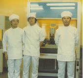
Figure 4 - Mr Nakazawa at the time the SAW filter was developed
This photograph was taken in 1977 or 1978, in the clean room of Toyo Communication Equipment Company's Shonan Plant (now known as the Shonan Plant of Seiko Epson).
By Technical Writer, Katsumi Yamashita
(To be continued)
interview
 |
Mr. Nakazawa joined Toyo Communication Equipment Company in 1953 after graduating from the Department of Electrical Communication, Faculty of Engineering at Tohoku University the same year. After joining the company, he was consistently involved in the development of quartz devices, including new devices such as CM filters, HCM filters and SAW filters, which were thereafter introduced to the world. In 1984, he was appointed manager of the Research & Development Division's Electro Mechanical Device Research Laboratory, and in 1992 he became the manager of the Nakazawa Special Research Laboratory. His hobbies include listening to classical music, watching movies, viewing Buddhist statues and admiring works of pottery and ceramics. He likes to say that "Art understands technology" (‘Gijutsu-ha Geijutsu-ni tsujiru’ in Japanese). |
QMEMS is a registered trademark of Seiko Epson Corporation.
